隆 Semiconductor
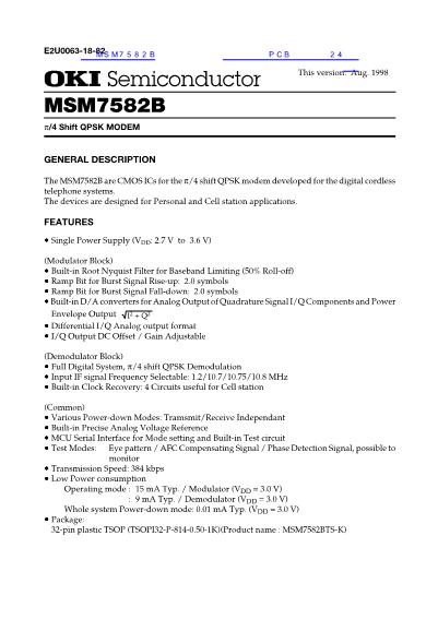
Demodulator Control Timing Diagram (Example)
Democulator unit
Modulator
input data
Timing for CS
PDN2
SLS2
SLS1
AFC
Slot 1
R1
MSM7582/7582B
Timing for PS
PDN2
SLS2
SLS1
AFC
(1) Control channel / synchronous burst (SS + PR = 64 bits)
RXD
AFC
(2) When synchronization is not established (for PS only)
AFC
(3) Communication channel (SS + PR = 8 bits)
RXD
AFC
���
����
���
���
,
���
���
����
��
Slot 2
R2
Slot 3
R3
Slot 4
R4
G
G
G
G
G
"0"
"0"
"0"
"1"
"1"
"0"
"1"
"1"
RXD
RXC
R1
R2
R3
R4
"0"
"0"
RXD
RXC
R1
240 bits 625
ms
64 bits
G G G G G G G G R R R R SS SS PR PR
PR UW
CR CR G G G G G G G G
RPR
RCW
56 bits
RPR
RCW
For PS, the window is initially open to
wait for the control signal from CS.
RPR is closed after UW is detected.
8 bits
G G G G G G G G R R R R SS SS PR PR
PR UW
CR CR G G G G G G G G
RPR
"0"
RCW
When the strength of the received wave is large
Less than 30 bits
When the strength of the received wave is small.
G :
R :
SS :
PR :
UW :
CR :
Guard bit
Ramp bit
Start symbol bit
Preamble bit
Unique word bit
CRC bit
23/24


 1
1
 2
2
 3
3
 4
4
 5
5
 6
6
 7
7
 8
8
 9
9
 10
10
 11
11
 12
12
 13
13
 14
14
 15
15
 16
16
 17
17
 18
18
 19
19
 20
20
 21
21
 22
22
 23
23
 24
24
