Philips Semiconductors
TEA5767HN
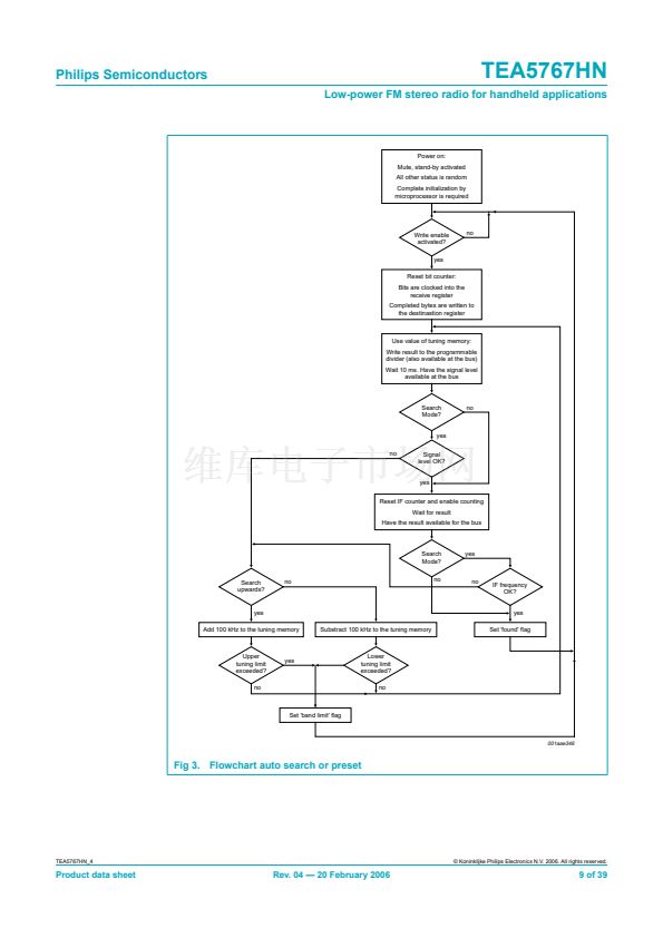
Low-power FM stereo radio for handheld applications
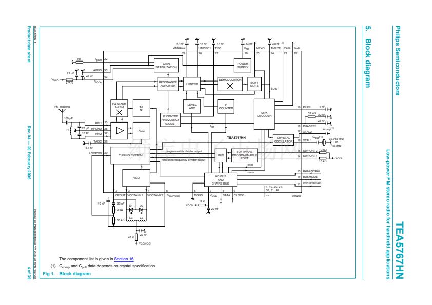
8. I
2
C-bus, 3-wire bus and bus-controlled functions
8.1 I
2
C-bus speci鏗乧ation
Information about the I
2
C-bus can be found in the brochure
鈥淭he I
2
C-bus and how to use
it鈥?(order number 9398 393 40011).
The standard I
2
C-bus speci鏗乧ation is expanded by the following de鏗乶itions:
IC address: 110 0000b
Structure of the I
2
C-bus logic: slave transceiver
Subaddresses are not used
The maximum LOW-level input and the minimum HIGH-level input are speci鏗乪d to
0.2V
CCD
and 0.45V
CCD
respectively.
The pin BUSMODE must be connected to ground to operate the IC with the I
2
C-bus.
Remark:
The I
2
C-bus operates at a maximum clock frequency of 400 kHz. It is not
allowed to connect the IC to an I
2
C-bus operating at a higher clock rate.
8.1.1 Data transfer
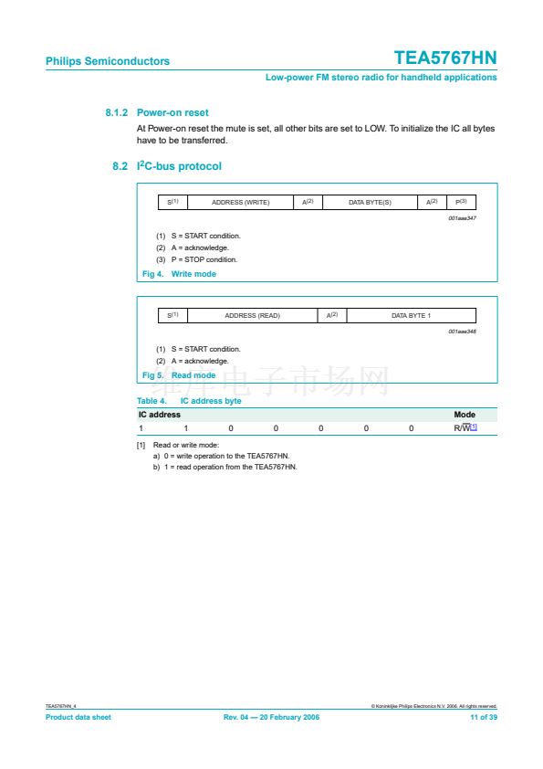
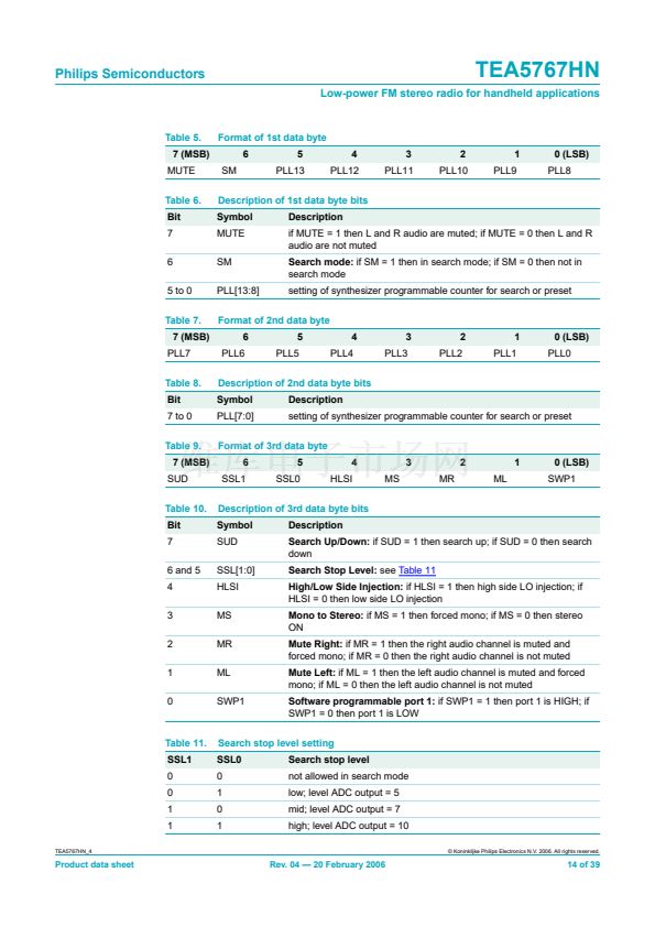
Data sequence: address, byte 1, byte 2, byte 3, byte 4 and byte 5 (the data transfer has to
be in this order). The LSB = 0 of the address indicates a WRITE operation to the
TEA5767HN.
Bit 7 of each byte is considered as the MSB and has to be transferred as the 鏗乺st bit of the
byte.
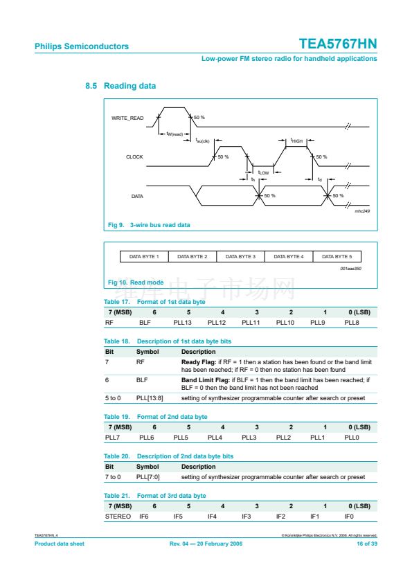
The data becomes valid bitwise at the appropriate falling edge of the clock. A STOP
condition after any byte can shorten transmission times.
When writing to the transceiver by using the STOP condition before completion of the
whole transfer:
鈥?/div>
The remaining bytes will contain the old information
鈥?/div>
If the transfer of a byte is not completed, the new bits will be used, but a new tuning
cycle will not be started
The IC can be switched into a low current Standby mode with the standby bit; the bus is
then still active. The standby current can be reduced by deactivating the bus interface
(pin BUSENABLE LOW). If the bus interface is deactivated (pin BUSENABLE LOW)
without the Standby mode being programmed, the IC maintains normal operation, but is
isolated from the bus lines.
The software programmable output (SWPORT1) can be programmed to operate as a
tuning indicator output. As long as the IC has not completed a tuning action,
pin SWPORT1 remains LOW. The pin becomes HIGH, when a preset or search tuning is
completed or when a band limit is reached.
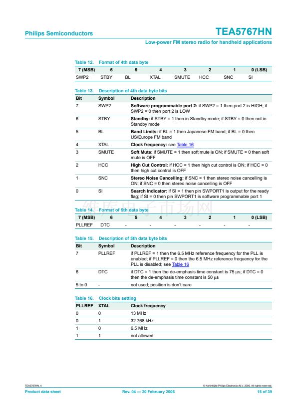
The reference frequency divider of the synthesizer PLL is changed when the MSB in
byte 5 is set to logic 1. The tuning system can then be clocked via pin XTAL2 at 6.5 MHz.
TEA5767HN_4
漏 Koninklijke Philips Electronics N.V. 2006. All rights reserved.
Product data sheet
Rev. 04 鈥?20 February 2006
10 of 39


 1
1
 2
2
 3
3
 4
4
 5
5
 6
6
 7
7
 8
8
 9
9
 10
10
 11
11
 12
12
 13
13
 14
14
 15
15
 16
16
 17
17
 18
18
 19
19
 20
20
 21
21
 22
22
 23
23
 24
24
 25
25
 26
26
 27
27
 28
28
 29
29
 30
30
 31
31
 32
32
 33
33
 34
34
 35
35
 36
36
 37
37
 38
38
 39
39
