Philips Semiconductors
TEA5767HN
Low-power FM stereo radio for handheld applications
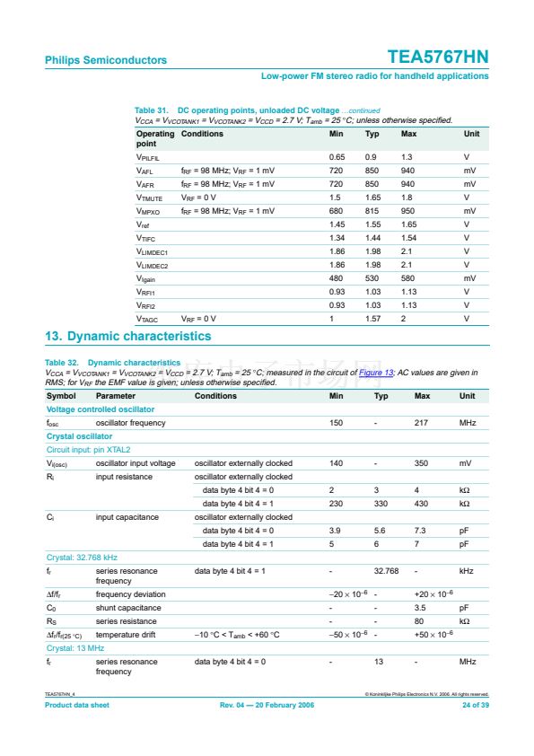
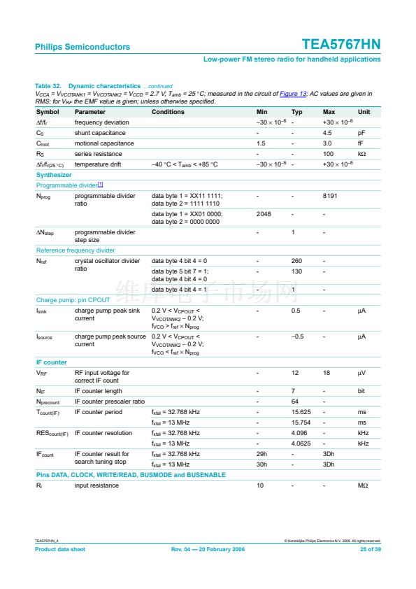
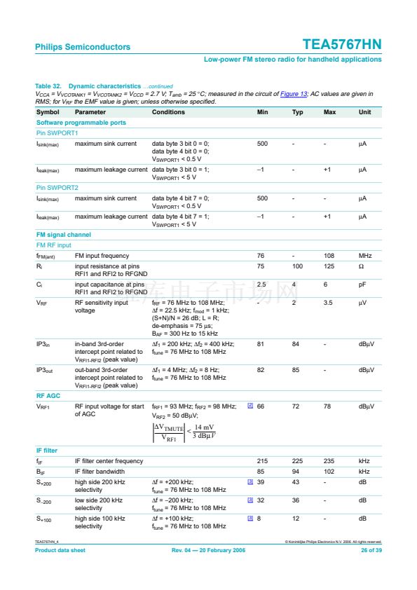
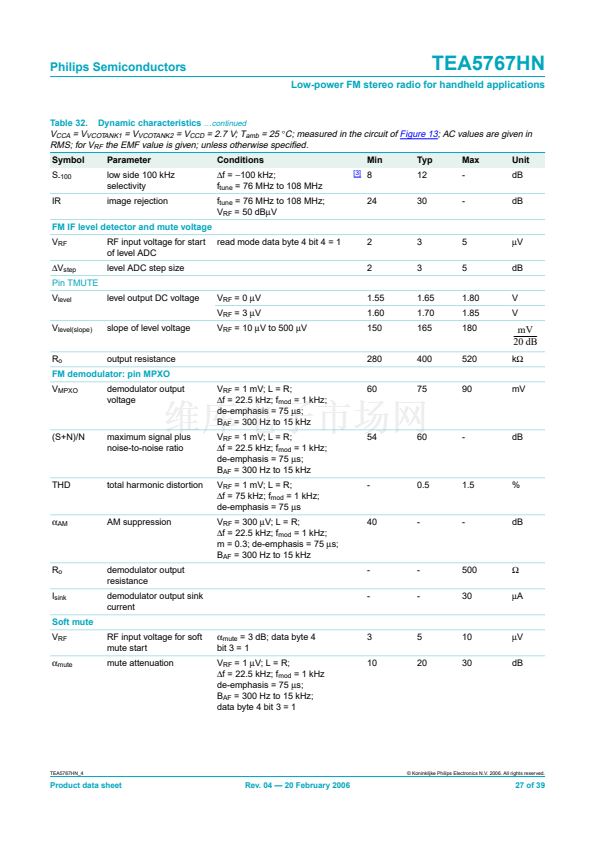
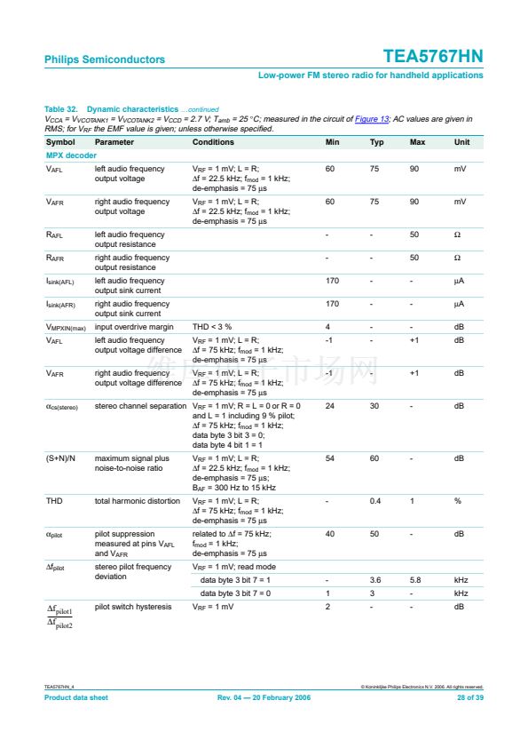
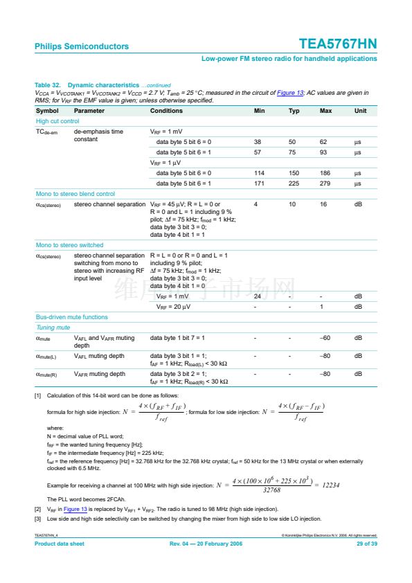
Table 32. Dynamic characteristics
鈥ontinued
V
CCA
= V
VCOTANK1
= V
VCOTANK2
= V
CCD
= 2.7 V; T
amb
= 25
擄
C; measured in the circuit of
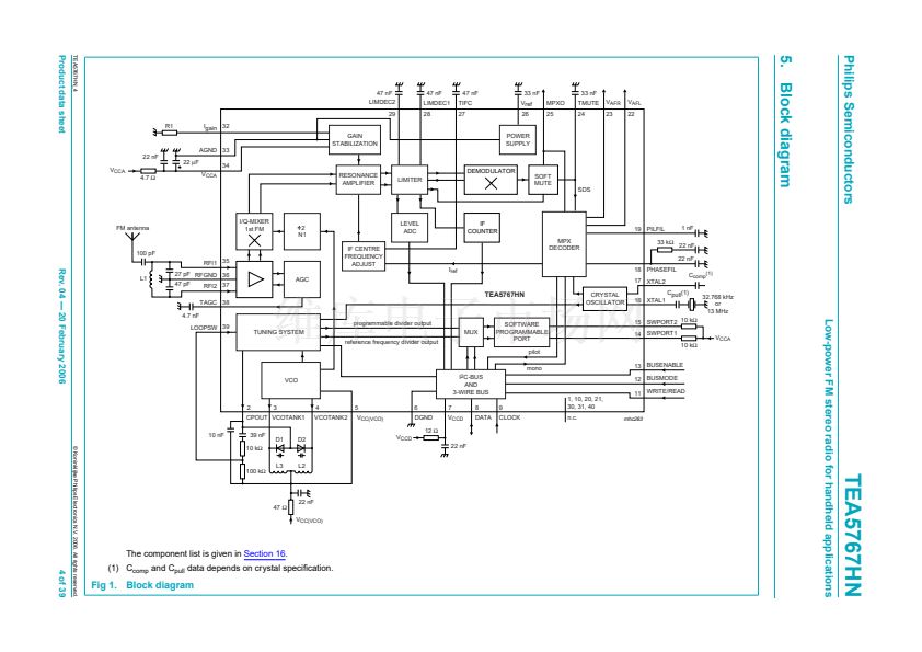
Figure 13;
AC values are given in
RMS; for V
RF
the EMF value is given; unless otherwise speci鏗乪d.
Symbol
S
-100
IR
Parameter
low side 100 kHz
selectivity
image rejection
Conditions
鈭唂
=
鈭?00
kHz;
f
tune
= 76 MHz to 108 MHz
f
tune
= 76 MHz to 108 MHz;
V
RF
= 50 dB碌V
read mode data byte 4 bit 4 = 1
[3]
Min
8
24
Typ
12
30
Max
-
-
Unit
dB
dB
FM IF level detector and mute voltage
V
RF
鈭哣
step
Pin TMUTE
V
level
V
level(slope)
R
o
V
MPXO
level output DC voltage
slope of level voltage
V
RF
= 0
碌V
V
RF
= 3
碌V
V
RF
= 10
碌V
to 500
碌V
1.55
1.60
150
1.65
1.70
165
1.80
1.85
180
V
V
RF input voltage for start
of level ADC
level ADC step size
2
2
3
3
5
5
碌V
dB
mV
-------------
-
20 dB
k鈩?/div>
mV
output resistance
demodulator output
voltage
V
RF
= 1 mV; L = R;
鈭唂
= 22.5 kHz; f
mod
= 1 kHz;
de-emphasis = 75
碌s;
B
AF
= 300 Hz to 15 kHz
V
RF
= 1 mV; L = R;
鈭唂
= 22.5 kHz; f
mod
= 1 kHz;
de-emphasis = 75
碌s;
B
AF
= 300 Hz to 15 kHz
V
RF
= 1 mV; L = R;
鈭唂
= 75 kHz; f
mod
= 1 kHz;
de-emphasis = 75
碌s
V
RF
= 300
碌V;
L = R;
鈭唂
= 22.5 kHz; f
mod
= 1 kHz;
m = 0.3; de-emphasis = 75
碌s;
B
AF
= 300 Hz to 15 kHz
280
60
400
75
520
90
FM demodulator: pin MPXO
(S+N)/N
maximum signal plus
noise-to-noise ratio
54
60
-
dB
THD
total harmonic distortion
-
0.5
1.5
%
偽
AM
AM suppression
40
-
-
dB
R
o
I
sink
Soft mute
V
RF
偽
mute
demodulator output
resistance
demodulator output sink
current
RF input voltage for soft
mute start
mute attenuation
偽
mute
= 3 dB; data byte 4
bit 3 = 1
V
RF
= 1
碌V;
L = R;
鈭唂
= 22.5 kHz; f
mod
= 1 kHz
de-emphasis = 75
碌s;
B
AF
= 300 Hz to 15 kHz;
data byte 4 bit 3 = 1
-
-
-
-
500
30
鈩?/div>
碌A(chǔ)
3
10
5
20
10
30
碌V
dB
TEA5767HN_4
漏 Koninklijke Philips Electronics N.V. 2006. All rights reserved.
Product data sheet
Rev. 04 鈥?20 February 2006
27 of 39


 1
1
 2
2
 3
3
 4
4
 5
5
 6
6
 7
7
 8
8
 9
9
 10
10
 11
11
 12
12
 13
13
 14
14
 15
15
 16
16
 17
17
 18
18
 19
19
 20
20
 21
21
 22
22
 23
23
 24
24
 25
25
 26
26
 27
27
 28
28
 29
29
 30
30
 31
31
 32
32
 33
33
 34
34
 35
35
 36
36
 37
37
 38
38
 39
39
