Philips Semiconductors
TEA5767HN
Low-power FM stereo radio for handheld applications
Pin description
鈥ontinued
Pin
17
18
19
20
21
22
23
24
25
26
27
28
29
30
31
32
33
34
35
36
37
38
39
40
Description
crystal oscillator input 2
phase detector loop 鏗乴ter
pilot detector low-pass 鏗乴ter
not connected
not connected
left audio frequency output voltage
right audio frequency output voltage
time constant for soft mute
FM demodulator MPX signal output
reference voltage
time constant for IF center adjust
decoupling IF limiter 1
decoupling IF limiter 2
not connected
not connected
gain control current for IF 鏗乴ter
analog ground
analog supply voltage
RF input 1
RF ground
RF input 2
time constant RF AGC
switch output of synthesizer PLL loop 鏗乴ter
not connected
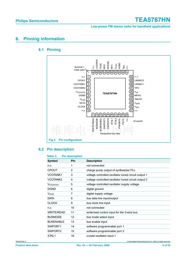
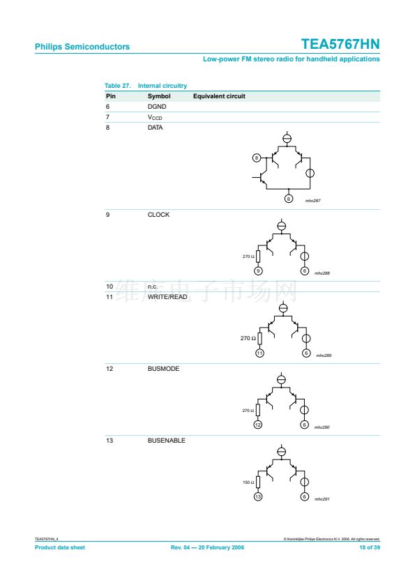
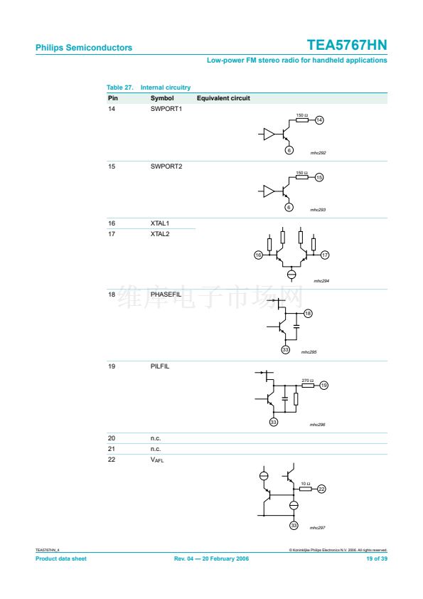
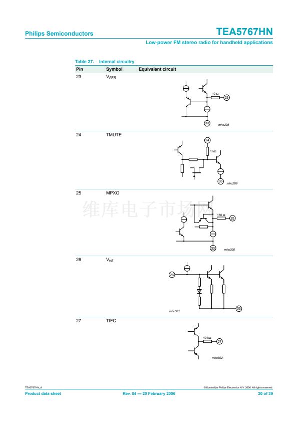
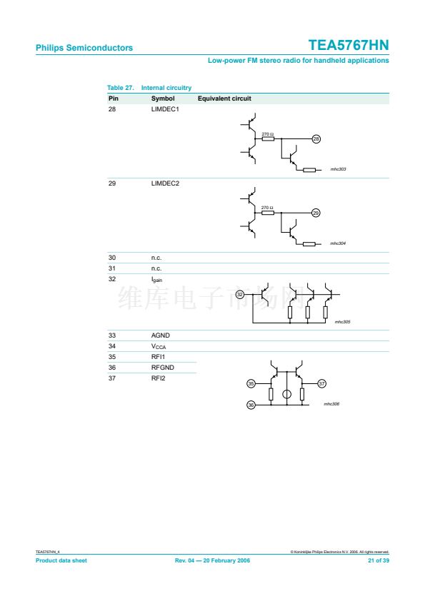
Table 3.
Symbol
XTAL2
PHASEFIL
PILFIL
n.c.
n.c.
V
AFL
V
AFR
TMUTE
MPXO
V
ref
TIFC
LIMDEC1
LIMDEC2
n.c.
n.c.
I
gain
AGND
V
CCA
RFI1
RFGND
RFI2
TAGC
LOOPSW
n.c.
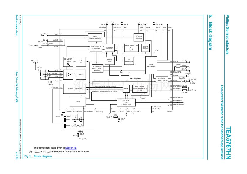
7. Functional description
7.1 Low-noise RF ampli鏗乪r
The Low Noise Ampli鏗乪r (LNA) input impedance together with the LC RF input circuit
de鏗乶es an FM band 鏗乴ter. The gain of the LNA is controlled by the RF AGC circuit.
7.2 FM mixer
The FM quadrature mixer converts the FM RF (76 MHz to 108 MHz) to an IF of 225 kHz.
7.3 VCO
The varactor tuned LC VCO provides the Local Oscillator (LO) signal for the FM
quadrature mixer. The VCO frequency range is 150 MHz to 217 MHz.
TEA5767HN_4
漏 Koninklijke Philips Electronics N.V. 2006. All rights reserved.
Product data sheet
Rev. 04 鈥?20 February 2006
6 of 39


 1
1
 2
2
 3
3
 4
4
 5
5
 6
6
 7
7
 8
8
 9
9
 10
10
 11
11
 12
12
 13
13
 14
14
 15
15
 16
16
 17
17
 18
18
 19
19
 20
20
 21
21
 22
22
 23
23
 24
24
 25
25
 26
26
 27
27
 28
28
 29
29
 30
30
 31
31
 32
32
 33
33
 34
34
 35
35
 36
36
 37
37
 38
38
 39
39
