Serially Interfaced, +2.7V to +5.5V,
5- and 8-Digit LED Display Drivers
MAX6950/MAX6951
CS
t
CSW
t
CSS
t
CL
t
CH
t
CP
t
CSH
CLK
t
DS
DIN
t
DH
D14
D1
D0
D15
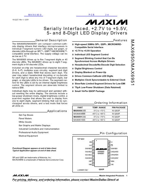
Figure 1. Timing Diagram
CS
CLK
DIN
D15
D14
D13
D12
D11
D10
D9
D8
D7
D6
D5
D4
D3
D2
D1
D0
Figure 2. Transmission of 16 Bits to the MAX6950/MAX6951
CS
CLK
DIN
BIT1
BIT2
N-15
N-14
N-13
N-12
N-11
N-10
N-9
N-8
N-7
N-6
N-5
N-4
N-3
N-2
N-1
N
Figure 3 . Transmission of More than 16 Bits to the MAX6950/MAX6951
grammed while in shutdown mode, and shutdown
mode can be overridden by the display test function.
Table 7 lists the blink rate selection format.
If blink is globally enabled by setting the E bit of the
configuration register (Table 8), then the digit data in
both planes P0 and P1 are used to control the display
(Table 9).
When the global blink timing synchronization bit is set,
the multiplex and blink timing counter is cleared on the
rising edge of
CS.
By setting the T bit in multiple
MAX6950/MAX6951s at the same time (or in quick suc-
cession), the blink timing can be synchronized across
all the devices.
When the global digit data clear (R data bit D5) is set,
the digit data for both planes P0 and P1 for ALL digits
is cleared on the rising edge of
CS.
Digits with decode
enabled display the zero. Digits without decode
enabled show all segments unlit.
_______________________________________________________________________________________
7


 1
1
 2
2
 3
3
 4
4
 5
5
 6
6
 7
7
 8
8
 9
9
 10
10
 11
11
 12
12
 13
13
 14
14
 15
15
 16
16
 17
17
 18
18
 19
19
