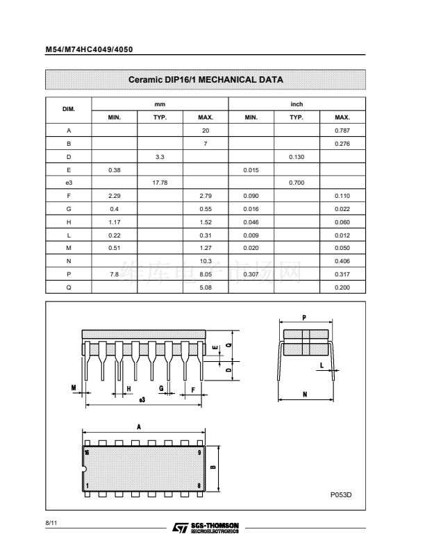
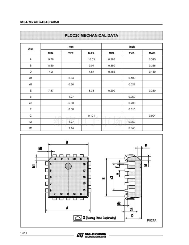
M54/M74HC4049/4050
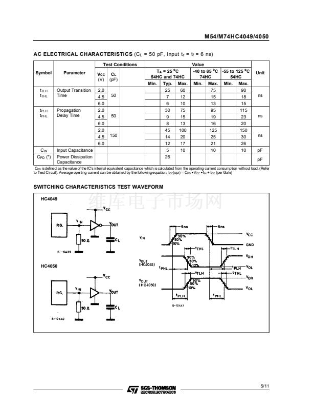
AC ELECTRICAL CHARACTERISTICS
(C
L
= 50 pF, Input t
r
= t
f
= 6 ns)
Test Conditions
Symbol
Parameter
V
CC
(V)
2.0
4.5
6.0
2.0
4.5
6.0
2.0
4.5
6.0
C
IN
C
PD
(*)
Input Capacitance
Power Dissipation
Capacitance
C
L
(pF)
T
A
= 25 C
54HC and 74HC
Min.
Typ.
25
7
6
30
9
8
45
14
12
5
26
Max.
60
12
10
75
15
13
100
20
17
10
o
Value
-40 to 85
o
C -55 to 125
o
C
74HC
54HC
Min.
Max.
75
15
13
95
19
16
125
25
21
10
Min.
Max.
90
18
15
115
23
20
150
30
26
10
Unit
t
TLH
t
THL
t
PLH
t
PHL
Output Transition
Time
Propagation
Delay Time
50
ns
50
ns
150
ns
pF
pF
C
PD
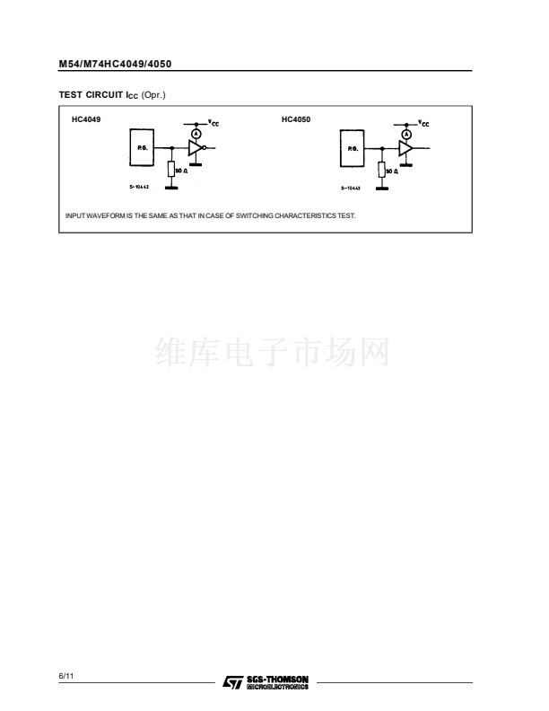
isdefined as the value of the IC鈥檚 internal equivalent capacitance which is calculated from the operating current consumption without load. (Refer
to Test Circuit). Average operting current can be obtained by the following equation. I
CC
(opr) = C
PD
鈥
CC
鈥
IN
+ I
CC
(per Gate)
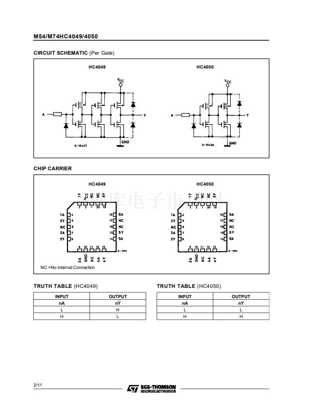
SWITCHING CHARACTERISTICS TEST WAVEFORM
HC4049
HC4050
5/11


 1
1
 2
2
 3
3
 4
4
 5
5
 6
6
 7
7
 8
8
 9
9
 10
10
 11
11
