CS5253B鈭?
6
5
4
ESR (W)
Unstable
3
2
Stable Region
1
0
V
POWER
= 3.3 V
V
CONTROL
= 5.0 V
I
LOAD
= 0 to 3.0 A
V
OUT
= 2.5 V
V
OUT
Shorted to V
SENSE
T
J
= 0擄C to 150擄C
0
10
20
30
40
50
60
70
80
90
100
Capacitance (mF)
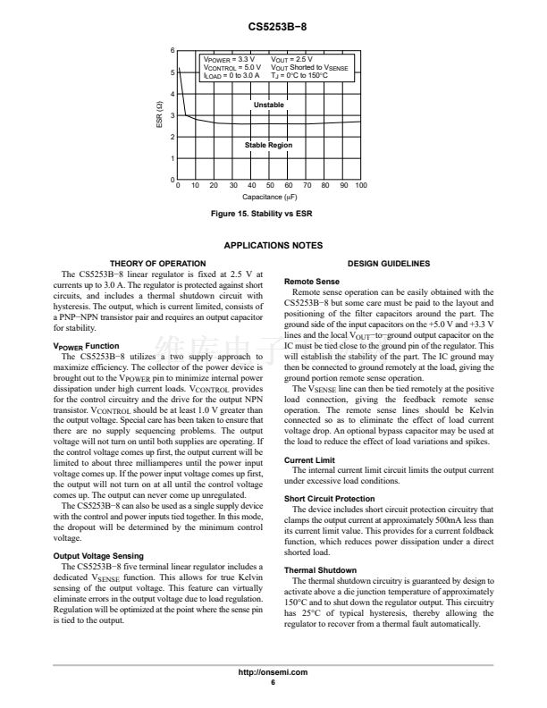
Figure 15. Stability vs ESR
APPLICATIONS NOTES
THEORY OF OPERATION
DESIGN GUIDELINES
Remote Sense
The CS5253B鈭? linear regulator is fixed at 2.5 V at
currents up to 3.0 A. The regulator is protected against short
circuits, and includes a thermal shutdown circuit with
hysteresis. The output, which is current limited, consists of
a PNP鈭扤PN transistor pair and requires an output capacitor
for stability.
V
POWER
Function
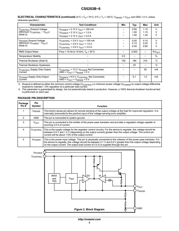
The CS5253B鈭? utilizes a two supply approach to
maximize efficiency. The collector of the power device is
brought out to the V
POWER
pin to minimize internal power
dissipation under high current loads. V
CONTROL
provides
for the control circuitry and the drive for the output NPN
transistor. V
CONTROL
should be at least 1.0 V greater than
the output voltage. Special care has been taken to ensure that
there are no supply sequencing problems. The output
voltage will not turn on until both supplies are operating. If
the control voltage comes up first, the output current will be
limited to about three milliamperes until the power input
voltage comes up. If the power input voltage comes up first,
the output will not turn on at all until the control voltage
comes up. The output can never come up unregulated.
The CS5253B鈭? can also be used as a single supply device
with the control and power inputs tied together. In this mode,
the dropout will be determined by the minimum control
voltage.
Output Voltage Sensing
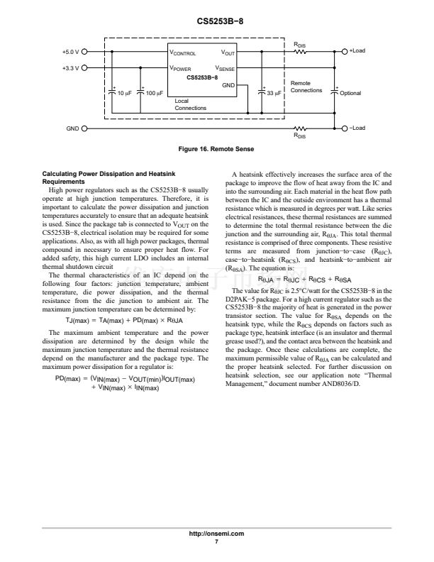
Remote sense operation can be easily obtained with the
CS5253B鈭? but some care must be paid to the layout and
positioning of the filter capacitors around the part. The
ground side of the input capacitors on the +5.0 V and +3.3 V
lines and the local V
OUT
鈭抰o鈭抔round output capacitor on the
IC must be tied close to the ground pin of the regulator. This
will establish the stability of the part. The IC ground may
then be connected to ground remotely at the load, giving the
ground portion remote sense operation.
The V
SENSE
line can then be tied remotely at the positive
load connection, giving the feedback remote sense
operation. The remote sense lines should be Kelvin
connected so as to eliminate the effect of load current
voltage drop. An optional bypass capacitor may be used at
the load to reduce the effect of load variations and spikes.
Current Limit
The internal current limit circuit limits the output current
under excessive load conditions.
Short Circuit Protection
The device includes short circuit protection circuitry that
clamps the output current at approximately 500mA less than
its current limit value. This provides for a current foldback
function, which reduces power dissipation under a direct
shorted load.
Thermal Shutdown
The CS5253B鈭? five terminal linear regulator includes a
dedicated V
SENSE
function. This allows for true Kelvin
sensing of the output voltage. This feature can virtually
eliminate errors in the output voltage due to load regulation.
Regulation will be optimized at the point where the sense pin
is tied to the output.
The thermal shutdown circuitry is guaranteed by design to
activate above a die junction temperature of approximately
150擄C and to shut down the regulator output. This circuitry
has 25擄C of typical hysteresis, thereby allowing the
regulator to recover from a thermal fault automatically.
http://onsemi.com
6


 1
1
 2
2
 3
3
 4
4
 5
5
 6
6
 7
7
 8
8
