MCP6546/6R/6U/7/8/9
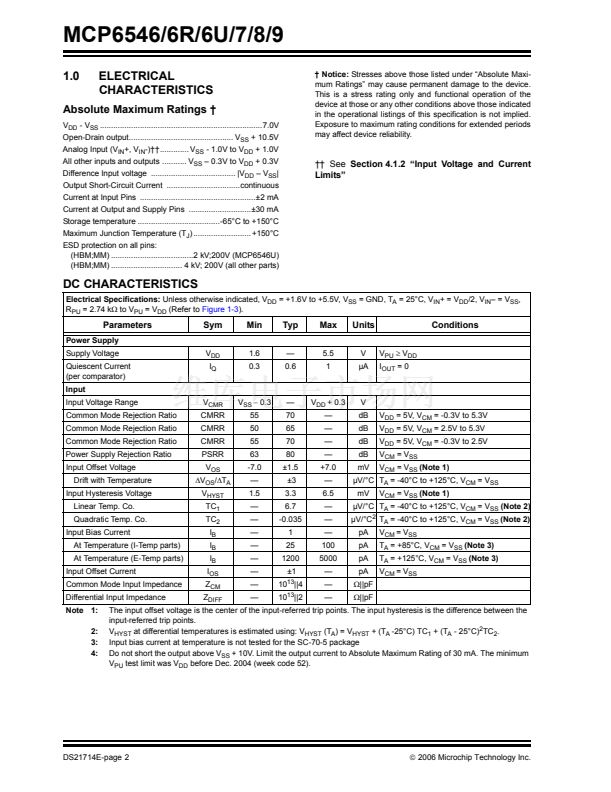
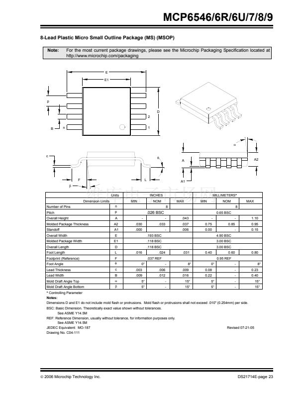
8-Lead Plastic Micro Small Outline Package (MS) (MSOP)
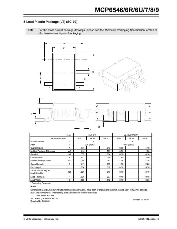
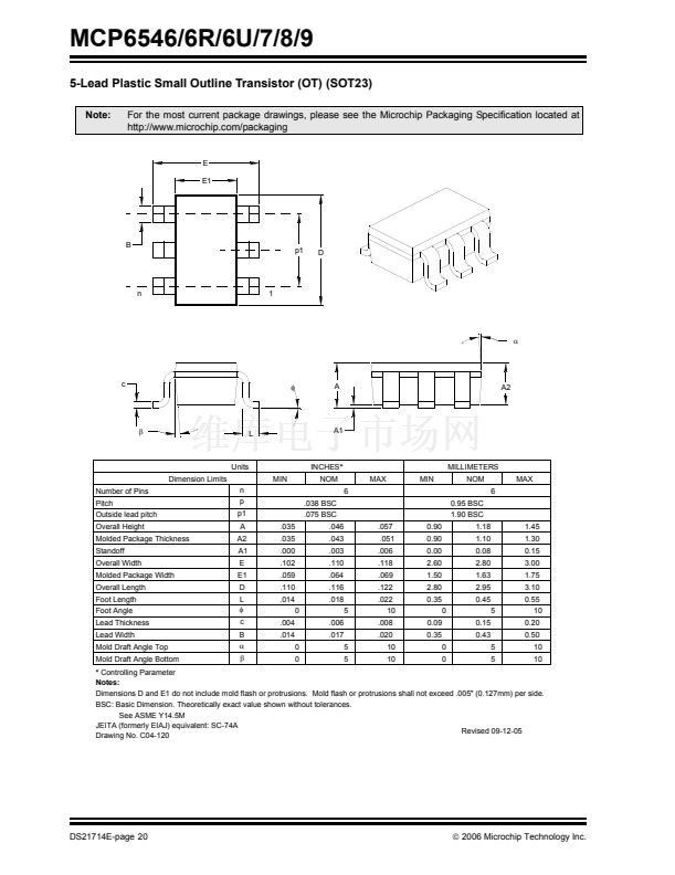
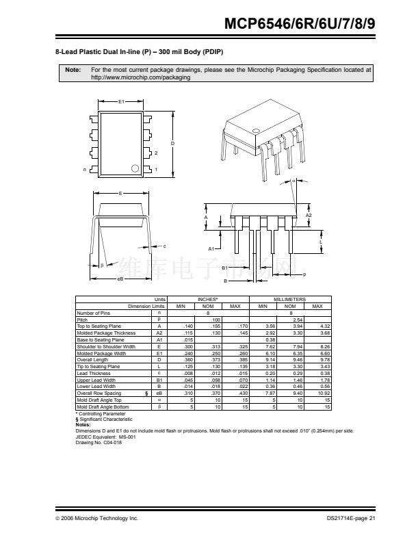
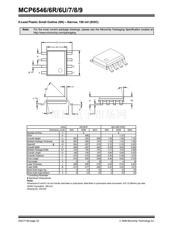
Note:
For the most current package drawings, please see the Microchip Packaging Specification located at
http://www.microchip.com/packaging
E
E1
p
D
2
B
n
1
偽
c
蠁
A
A2
F
尾
Units
Dimension Limits
Number of Pins
Pitch
Overall Height
Molded Package Thickness
Standoff
Overall Width
Molded Package Width
Overall Length
Foot Length
Footprint (Reference)
Foot Angle
Lead Thickness
Lead Width
Mold Draft Angle Top
Mold Draft Angle Bottom
n
p
A
A2
A1
E
E1
D
L
F
蠁
c
B
偽
尾
.016
-
.030
.000
MIN
L
A1
INCHES
NOM
8
MAX
MIN
MILLIMETERS*
NOM
8
0.65 BSC
-
.043
.037
.006
-
0.75
0.00
4.90 BSC
3.00 BSC
3.00 BSC
.031
8擄
.009
.016
15擄
15擄
0.40
0擄
0.08
0.22
5擄
5擄
0.60
0.95 REF
-
-
-
-
-
-
8擄
0.23
0.40
15擄
15擄
0.80
-
0.85
-
1.10
0.95
0.15
MAX
.026 BSC
.033
-
.193 BSC
.118 BSC
.118 BSC
.024
.037 REF
0擄
.003
.009
5擄
5擄
.006
.012
-
-
*
Controlling Parameter
Notes:
Dimensions D and E1 do not include mold flash or protrusions. Mold flash or protrusions shall not exceed .010" (0.254mm) per side.
BSC: Basic Dimension. Theoretically exact value shown without tolerances.
See ASME Y14.5M
REF: Reference Dimension, usually without tolerance, for information purposes only.
See ASME Y14.5M
JEDEC Equivalent: MO-187
Drawing No. C04-111
Revised 07-21-05
漏
2006 Microchip Technology Inc.
DS21714E-page 23


 1
1
 2
2
 3
3
 4
4
 5
5
 6
6
 7
7
 8
8
 9
9
 10
10
 11
11
 12
12
 13
13
 14
14
 15
15
 16
16
 17
17
 18
18
 19
19
 20
20
 21
21
 22
22
 23
23
 24
24
 25
25
 26
26
 27
27
 28
28
 29
29
 30
30
 31
31
 32
32
